Why Does a Liquid Filling Machine Underfill or Overfill?
Incorrect quantities are not always a timer problem. A practical sequence for checking measurements, product supply, nozzles, filling methods and PLC settings.
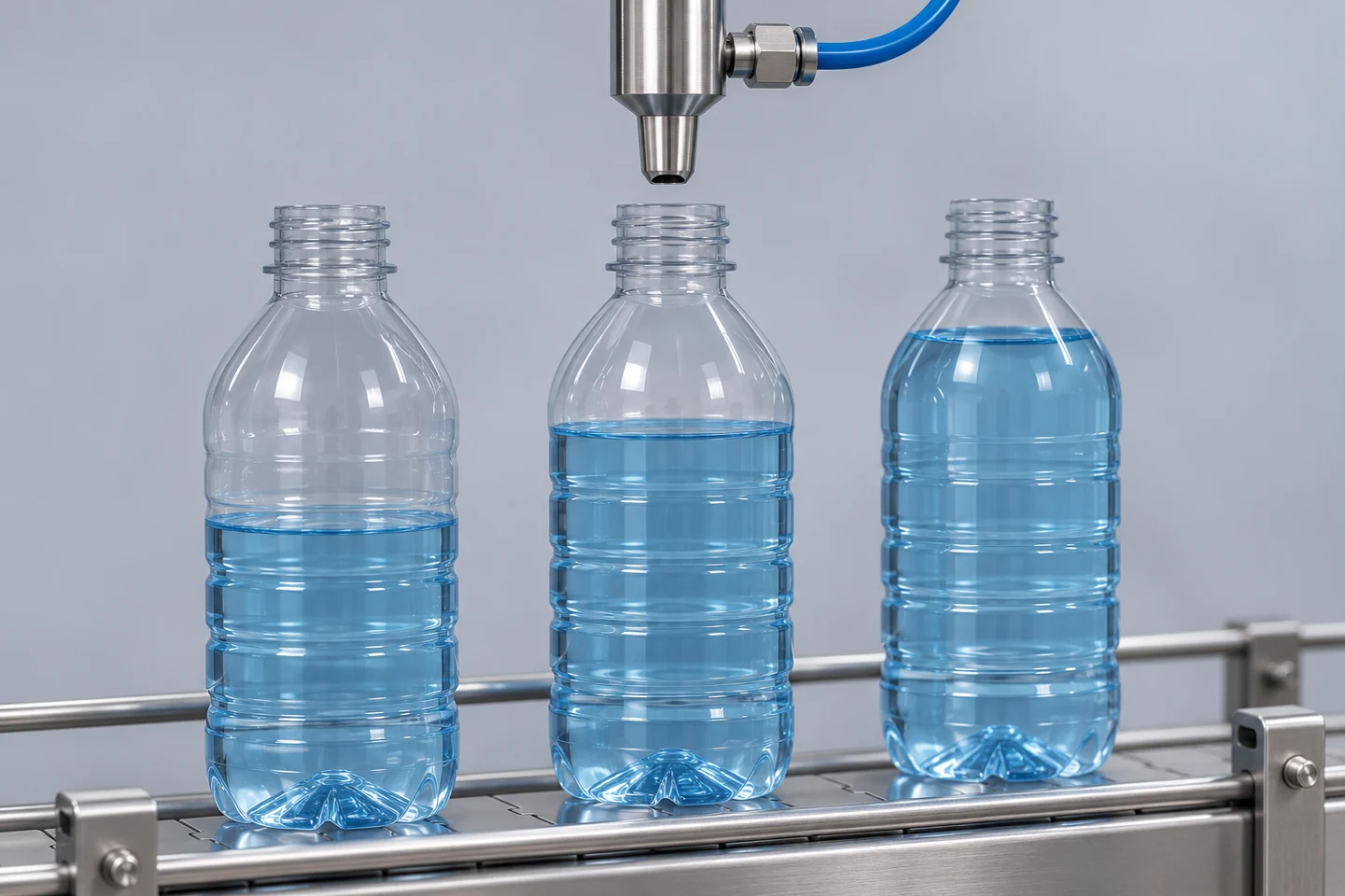
Underfilling or overfilling can result from measurement errors, changing flow, unstable product supply, nozzle dripping, mechanical wear or incorrect recipes and control settings. Start by measuring the pattern of the deviation rather than immediately changing the filling time.
Are all bottles low by a similar amount, do quantities vary unpredictably, or is only one nozzle different? These patterns may require different investigations. Diagrams and numerical examples in this article are illustrative. The generated cover image is not a production test record.
1. Check what you are actually measuring
Visible fill height alone is not a reliable quantity comparison. Internal bottle geometry can change the apparent level, and foam may make it look higher than the settled liquid.
Use a checked balance with suitable resolution. Establish the empty container tare, weigh the filled container and record net product mass. If empty containers vary, applying one bottle’s tare to every bottle can introduce an error. Keep your approach to settling foam and obtaining a stable reading consistent.
Grams and millilitres are different units. To check a volume target by mass, use the product density at the relevant temperature: mass = volume × density. As a calculation example only, 250 ml at 1.05 g/ml equals 262.5 g. Do not assume that density for your own product.
2. Separate a consistent offset from inconsistent fills
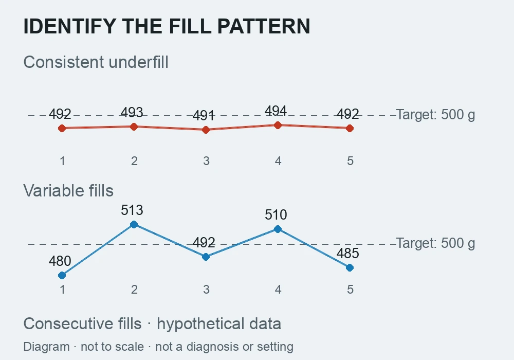
- Every fill is similarly low or high: review the recipe, calibration, target units and settings relevant to the filling method. A consistent supply problem can also produce an offset.
- Consecutive bottles vary: investigate supply stability, air ingress, valve behaviour and repeatable triggering.
- Only one nozzle differs: compare that channel’s hose, valve, nozzle, connections and any individual calibration.
- Deviation increases as the tank empties: check how supply level affects flow.
- The first bottle after a pause differs: consider drain-back, accumulated air or dripping during the pause.
These observations narrow the investigation; they are not proof of a particular fault. Record nozzle number, recipe, product temperature and tank level alongside the measured quantity.
3. Why can the same filling time give different quantities?
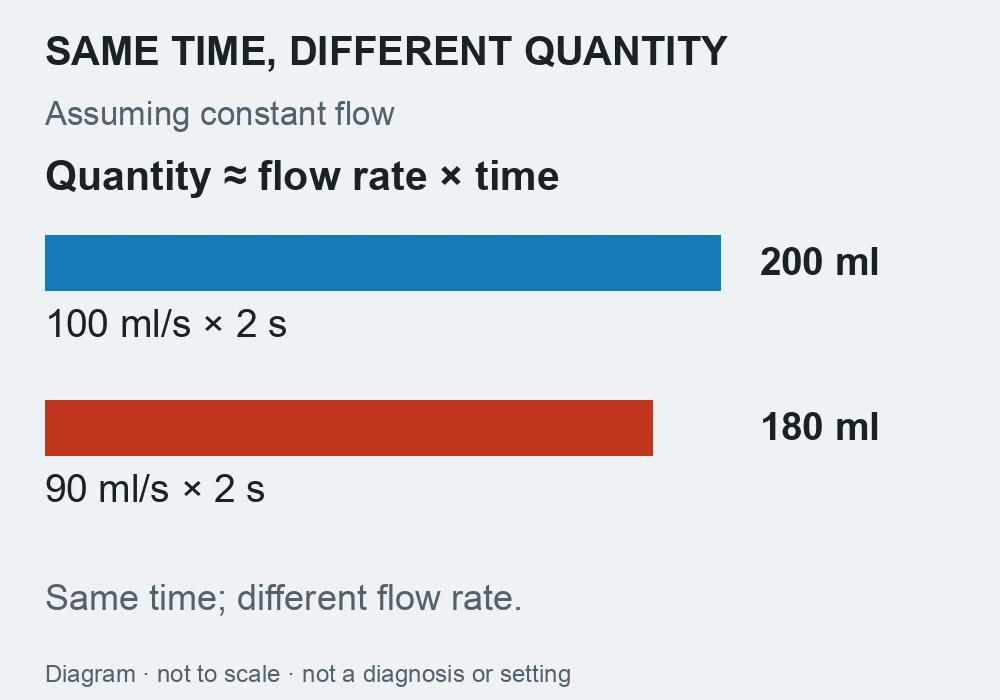
In timed filling, the amount delivered is the total flow over the filling interval. With the simplifying assumption of constant flow, quantity ≈ flow rate × time. A change in flow changes the quantity even when time stays the same.
For example, two seconds at a constant 100 ml/s gives 200 ml; at 90 ml/s it gives 180 ml. These are hypothetical values. Actual valve opening and closing transitions and flow changes during the cycle also matter.
Before increasing the timer, check whether supply level or pressure changes, whether product temperature or viscosity has changed, whether air is entering the suction line and whether a restriction, pump condition or filter condition affects delivery.
This relationship is not a universal adjustment rule for every filler. Piston stroke and chamber filling, flowmeter measurement and cutoff, or weighing and stopping behaviour must be assessed for the actual method.
4. Does the nozzle drip after filling stops?
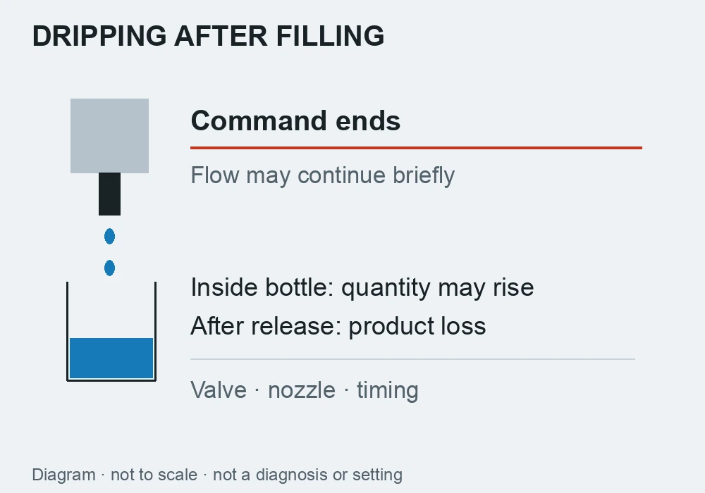
Ending the PLC fill command does not prove that physical flow stops at exactly the same instant. Valve response and product remaining in the nozzle can continue to influence the delivered amount.
From the designated safe observation position, note which nozzle drips and when. Product entering a bottle before it leaves may increase its fill; product falling after it leaves causes loss and contamination. Bottle-to-nozzle alignment also matters.
Valve seating, seals, pneumatic movement and any manufacturer-defined suck-back or cutoff settings may require maintenance review. Isolate machine energy safely before intervention on nozzles, pressurised lines or moving parts. Increasing suck-back indiscriminately is not a universal fix; its effect depends on the product and system.
5. What changes with piston, flowmeter and weight filling?
Piston filling: examine repeatable stroke, inlet/outlet valves, complete product supply to the chamber and sealing. A viscous product may not enter the chamber adequately under the available conditions. Extending an output timer does not address every piston-filling problem.
Flowmeter filling: check compatibility with the product, units, scaling or pulse factor and cutoff at the target. Do not confuse mass and volumetric flow measurements. Assess air and installation conditions against the specific meter’s instructions.
Weight filling: review tare, mechanical contact, vibration, stable readings and any coarse/fine filling transition. Product still in flight after stopping can contribute to overshoot. Apply pre-cutoff compensation only through the method supported by the system and verified measurements.
6. What should be compared in the PLC and HMI?
Confirm that the recipe selected on the screen matches the active values in the PLC. Seconds, milliseconds, grams and millilitres must match the program’s units and scaling.
Trace bottle detection, position confirmation, fill start, fill completion and bottle release for a cycle. Sensor chatter or incorrect triggers can produce incomplete cycles or repeated commands, depending on the application. Define when changes made during a cycle take effect.
The filling machine HMI screen guide illustrates useful operator information. Changes to sequence logic or recipe transfer belong in the scope of PLC and HMI programming. Software cannot replace stable mechanical supply or repair a faulty valve.
7. A short sequence before changing settings
- Record product, recipe, target and measurement unit.
- Measure consecutive fills using the same method and known container tares. A small initial record, such as 5–10 fills, can support fault investigation; it is not statistical process validation or a product acceptance plan.
- Separate results by nozzle where there are multiple channels.
- Compare supply conditions, air, dripping and cycle sequence.
- Have an authorised person change one parameter in accordance with the machine instructions, recording before-and-after results.
- Recheck startup, continuous running and conditions after a pause. One acceptable bottle is not sufficient evidence.
Acceptance limits depend on the product specification, process requirements and applicable rules. This article does not prescribe a universal tolerance percentage.
Frequently asked questions
Will increasing filling time fix underfilling?
It may increase quantity in a stable timed system. With air ingress, variable flow or a valve fault, increasing time can leave the inconsistency unresolved and overfill some bottles.
Does a low visible level always mean an underfill?
No. Container geometry, foam and settling affect appearance. Check net quantity using the defined measurement method.
Must filling errors be caused by PLC software?
No. Measurement, supply, mechanics and control need to be assessed together. Active recipe values and cycle records help distinguish a control deviation from changing physical flow.
Manufacturer references
- FILAMATIC: questions about foaming, variable filling speeds and dripping
- Watson-Marlow Quantum 600 user manual: flow calibration
These references describe specific equipment. Use the current instructions for your own machine, pump and measuring device when adjusting or maintaining them.